Bright-Target mask computation
Bright target on SAR images are manifestations of extreme return due to target with significantly higher back-scattered signal (boats, wind turbines, …) compared to background. Bright target strongly affect most of significant radar quantities computation such as cross-section, normalized variance or image cross-spectrum evaluation. To derive significant estimation of these radar parameters (from a sea-state estimation perspective), these bright targets must be, as much as possible, removed from the original data before applying conventional algorithms. To this purpose, we will rely on the Cell-Averaging CFAR (Constant False Alarm Rate) algorithm to identify the bright target location. The CFAR method spots (Cell-averaging) bright targets having significantly different signal statistical characteristics compared to the surounding (clutter) cells. A guard distance (guard cells) from the target location ensures to keep bright target spatial contamination from the reference clutter (training cells).
The CA-CFAR algorithm is applied on the absolute value of Digital Numbers \(|\widetilde{DN}|\).
The bright target mask is computed as follow:
define a target typical size [m] and corresponding number of pixels
define a guard size [m] (\(g_{rg}, g_{az}\)) and corresponding number of pixels
define a clutter size [m] (\(c_{rg}, c_{az}\)) and corresponding number of pixels
Convolve original data by a uniform kernel having target typical sizes. Resulting data writes \(\langle t \rangle\)
Define a cluster kernel based on the aforementioned guard and clutter sizes.
The convolving kernel writes:
where \(g_{rg}, g_{az}, c_{rg}, c_{az}\) respectively stands for guard sizes and clutter sizes in range and azimuth direction.
Convolving the original (respectively abs-squared) data with this kernel provide reference clutter mean \(\langle c \rangle\) and variance \(\langle(c-\langle c \rangle)^2\rangle\) per pixel.
Difference of target mean and reference mean normalized by square root of reference standard deviation gives a relative normalized ratio \(r_T\) that is to compare with a fixed treshold \(BT_{treshold}\).
Bright target mask is defined as follow
Original data is masked with the resulting \(BT_{mask}\) and steps 5 to 7 is then recursively applied. The recursive operation progressively remove targets that could have been missed in previous iteration du to spatial contamination of another close target.
9. An optional additional procedure called neighbor filtering can be applied after step 7. Synthetic Aperture Radar azimuthal compression makes bright targets signature to span over a larger distante than the actual size of the bright target. As a consequence, it is common to have spread brigh points around a stronger bright target. To remove such points, bright target mask derived in step 7 is dilated (binary dilation) and relative ratio \(r_T\) of points in the dilation radius are tested against a neighboor treshold \(BT'_{treshold}\) smaller than \(BT_{treshold}\). Bright target mask is dilated for dilated pixels where \(r_T>BT'_{treshold}\).
Typical values for parameters listed in this procedure are: \((t_{rg}, t_{az})=(5 m,5 m), (g_{rg}, g_{az})=(350 m,350 m), (c_{rg}, c_{az})=(1 km,1 km), BT_{treshold}=10, BT'_{treshold}=5\).
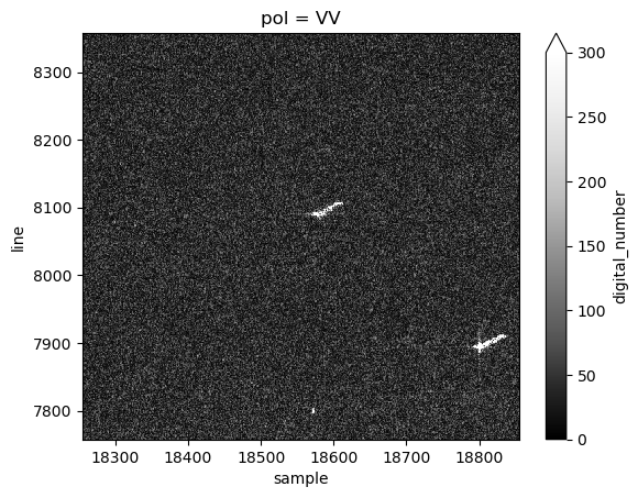
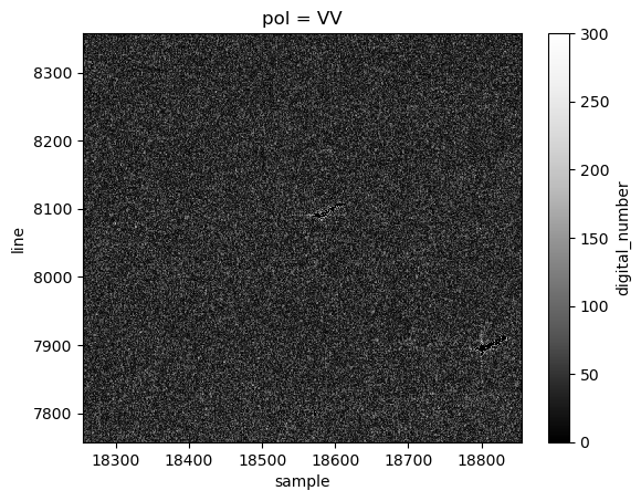
Illustration of the algorithm on the first subswath in VV polarisation coming from S1A_IW_SLC__1SDV_20220612T173328_20220612T173355_043633_05359A_1153.SAFE.
Before:

After:
